At Lenze, we address the issue of safety technology with Centralized/Decentralized Safety. Dangers for operating and maintenance personnel also emanate from the moving parts of the machines. It is essential to protect employees from these risks at all times - the most effective way to do this is to intervene at the point in the machine where the hazardous movement occurs - directly in the drive.
Certified
Since the safety functions integrated in the drive already have EC type approval, acceptance of the entire machine (e.g. by TÜV or the employers' liability insurance association) is simplified. The safety modules are certified according to EN ISO 13849-1, EN IEC 61508 and EN IEC 62061 and achieve the highest performance level PL e.
Direct connection
For the integration of Centralized/Decentralized Safety into the safety chain of your machine, safely executed inputs are available for the safety sensor technology. The connection to a higher-level PLC, which processes both standard and safety logic, is made via bus systems that can simultaneously transmit safe and unsafe data on a physical bus system - e.g. PROFIsafe or FSoE.
Simplified planning
We support you in implementing your safety requirements with the safety technology that can be integrated as an option. All functions are developed according to IEC 61508, SIL 3 and meet the requirements of EN ISO 13849-1 PL e as well as EN IEC 62061 SIL 3. This simplifies the acceptance of your entire machine.
Safety topology
Functional safety in the drive means that safety topologies can be implemented with very little wiring effort. The PLC Designer engineering tool, which can be used throughout, allows the safety aspects to be integrated very conveniently into the machine's stand-alone application. No system change is necessary, since standards (PLCopen) are used. The programming, setup and operation of the system can be created consistently with the tool. Operation and diagnosis is done directly or via a bus system.
Safety topologies EtherCAT
A very high-quality solution is a safety topology via EtherCAT with its extension FSoE (Functional Safety over EtherCAT). This solution is a very modern and high-performance bus system. By using EtherCAT, the drives can be controlled quite easily and further peripheral components can be connected.
Third party components
In many applications, it is necessary to integrate not only the drives into the safety topology, but also other components, so-called "third party components". When using EtherCAT/FSoE, Lenze has consistently adhered to the associated standards. This means that integration is possible without any problems. These components can be integrated without system breaks and contribute to the implementation of the machine's safety functions.
Twice as informed: Two white papers on Functional Safety
Machinery Directive & Machinery Regulation – explained concisely, prepared for practical use
Twice as informed: Two white papers on Functional Safety
Machinery Directive & Machinery Regulation – explained concisely, prepared for practical use
With two white papers, Lenze offers you a compact overview of the most important legal foundations for machine safety: the current Machinery Directive and the new Machinery Regulation. This gives you, as a machine builder, valuable information on legal requirements, implementation tips, and practical application examples.
The white papers show which obligations manufacturers must fulfil throughout the entire lifecycle and all operating modes, what consequences may arise from non-compliance, including personal liability for management, and how functional safety can be leveraged as an opportunity.
The interaction between safety and security is also highlighted: What was often seen as a contradiction in the past must now be considered and implemented together. In addition, three concrete practical examples illustrate how functional safety creates direct added value in practice. You will also find literature references to standards, directives, and important interpretation papers.
Benefit from this double package of expertise – for more safety, clarity, and future security in your machine development.
Five steps to a safe machine
The Machinery Directive comprises the following elements:
Carrying out a risk assessment: This enables you to identify applicable safety and health protection requirements.
- Design and construction of the machine that takes into account the results of the risk assessment.
- Following the risk assessment, you will know what measures you need to implement to reduce the risks.
If you cannot implement these measures in the design phase, then it will be necessary to integrate them into the control technology and set them down in writing in the specifications for the safety functions.
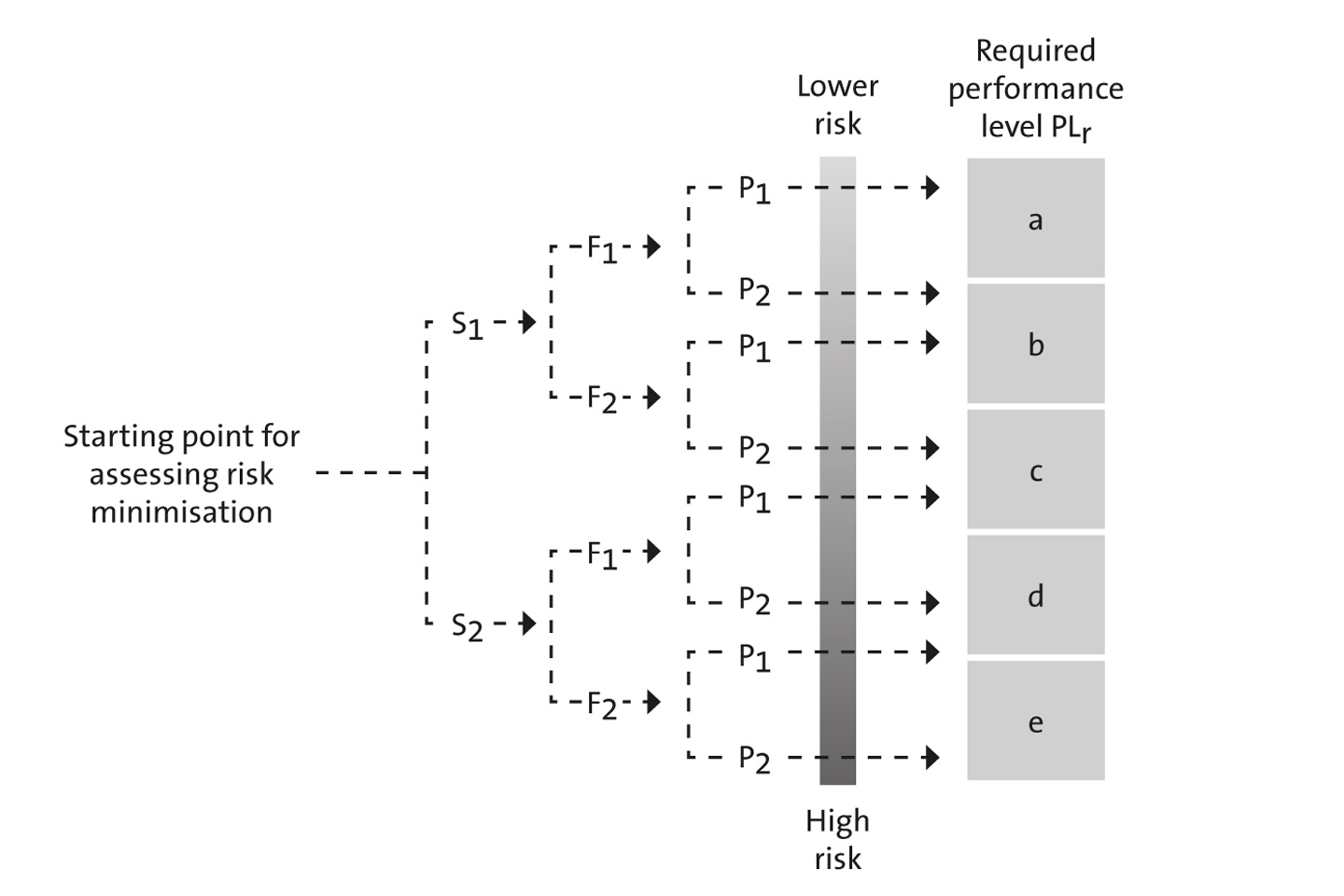
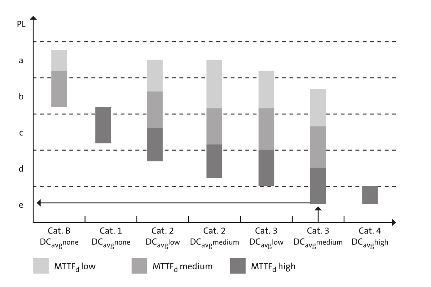
When using a control system, the Performance Level (PL) determines the requirements that the measures will need to meet in order to reduce risk. Following the implementation of safety functions, the real achieved PL will be checked and must be at least the same or greater than that worked out in theory beforehand.

